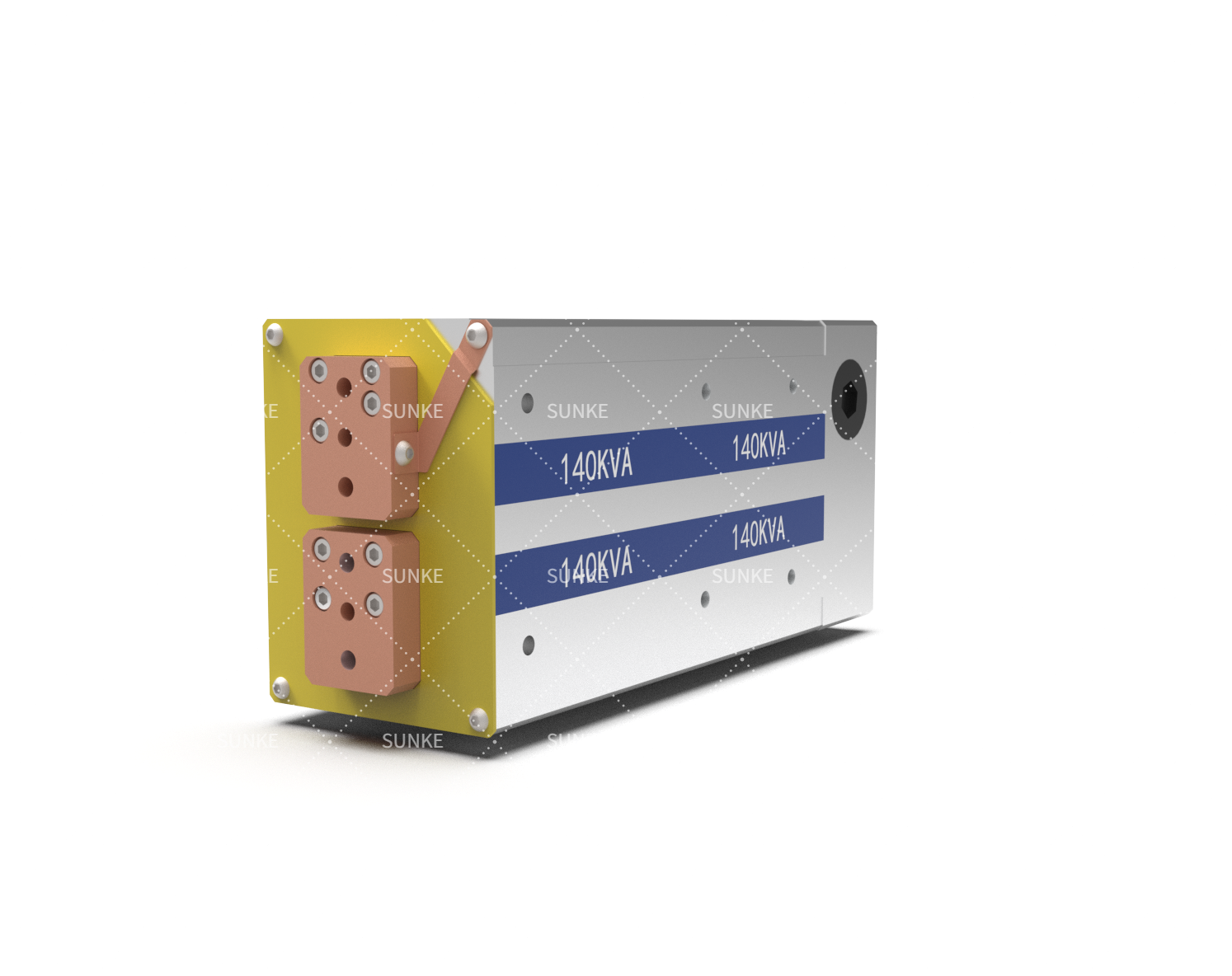
Choosing an MFDC transformer for an automated production line can appear straightforward: determine the required power, select a suitable model, and connect it to the welding controller.
Problems usually emerge later. A transformer may satisfy its nominal specification yet fail to deliver the expected welding performance once cable layout, tooling, cooling, duty cycle, and controller behavior enter the equation.
For automotive, battery, motor, electronics, and new-energy manufacturing, avoiding these integration mistakes is therefore as important as comparing transformer ratings.
Starting the Selection From Transformer Rating Alone
One frequent mistake is treating transformer power as the starting point of the engineering decision. The actual weld should come first. Material thickness, joint configuration, electrode arrangement, required current, weld time, production rhythm, and available cooling capacity collectively determine what the power system must deliver.
A catalog rating does not describe every operating condition. Two welding stations can require substantially different transformer configurations even when they perform similar-looking spot welds because their secondary circuits, tooling, and production cycles differ.
The selection of a resistance welding transformer should consequently follow the process specification rather than precede it. Engineers can first establish the demanding weld condition and then determine the electrical and thermal margin needed around that condition.
Overlooking the Electrical Path Between Transformer and Weld
Current does not stop at the transformer terminals. It travels through the secondary connections, busbars or cables, welding gun, electrodes, and workpiece before completing the circuit. Every additional connection or unsuitable conductor arrangement can influence the electrical behavior seen at the weld.
That detail becomes especially relevant in compact automated cells. A transformer positioned far from the welding gun can require a longer secondary connection, while cramped routing may introduce unnecessary bends or connection points. Maintenance access matters too: loose or degraded connections can change circuit conditions after months of production.
An MFDC welding transformer should therefore be evaluated together with the intended secondary circuit. The physical distance between components, connection method, conductor configuration, and welding-tool arrangement deserve attention during system design rather than after the equipment arrives.
Creating a Mismatch Between Power Supply and Welding Process
Another mistake occurs when the transformer and inverter are specified independently. An MFDC system depends on coordinated behavior between its power electronics, transformer, controller, and welding load. A component with an impressive individual specification is not automatically the right component for the complete system.
Process development can expose this mismatch quickly. Engineers may need precise control over welding current and time while the production cell imposes particular requirements on communication, triggering, sequencing, or parameter management. If those requirements are not established early, integration work can turn into a series of hardware and software adjustments.
Sunke approaches its transformer offering as part of the broader resistance welding equipment chain, with product configurations intended for different welding requirements. That perspective is useful because transformer selection is ultimately a system-engineering task, not simply a component purchase.
Leaving Mechanical and Cooling Constraints Until Installation
Electrical specifications receive considerable attention during purchasing, while physical integration is sometimes postponed until the machine builder starts assembly. That can create avoidable redesign work.
Transformer dimensions, mounting orientation, cable access, water connections, and proximity to the welding tool can all affect the final cell arrangement. Cooling deserves similar treatment. High production frequency and repeated high-current welding create a thermal load that must be considered against the selected operating duty cycle and cooling arrangement.
Their transformer information includes water-cooled configurations and different rated operating conditions. Such details should be reviewed against the actual production schedule, rather than assuming that any cooling-equipped unit will automatically suit a high-volume welding cell.
The practical question is not merely whether cooling exists. Engineers need to establish whether the complete cooling arrangement can support the intended operating pattern without becoming a production constraint.
Commissioning the Equipment Without Process-Level Validation
A machine can power up successfully and still require substantial process correction. Checking input power, control signals, water flow, and basic communication confirms that the equipment is functioning, but it does not prove that the welding process is stable.
Commissioning should move toward representative production conditions. Engineers can examine whether the required current and weld schedule remain consistent across repeated cycles, whether tooling introduces unexpected variation, and whether thermal behavior remains acceptable during sustained operation.
Sunke provides transformer configurations incorporating monitoring and protection-related functions, which can support a more controlled approach to system integration. The broader lesson is that commissioning should connect equipment checks with actual weld-process requirements.
Making Supplier Support an Afterthought
A supplier’s role should not end when the transformer is shipped. Difficulties often arise at the boundaries between the transformer, inverter, controller, welding gun, cooling system, and machine architecture. Early technical discussion can expose these interfaces before they become expensive field problems.
Useful supplier discussions should cover the intended weld schedule, current demand, installation arrangement, cooling conditions, secondary connections, controller pairing, and environmental constraints. Documentation should also make clear which operating parameters are applicable to the selected configuration.
For manufacturing engineers, this information is more valuable than a generic claim of high performance. The right supplier is one that can translate the welding application’s requirements into a workable transformer configuration and help the integrator verify that configuration within the complete cell.
Ultimately, the most common selection mistakes come from viewing the transformer as an isolated product. A resistance welding transformer has to work within a specific electrical, mechanical, thermal, and control environment. Defining that environment before purchasing, then validating it during integration, gives manufacturers a much stronger basis for stable production.
An MFDC welding transformer should be chosen as one component of the entire welding architecture for demanding automated lines. Many of the expensive adjustments that would otherwise only show up after installation can be avoided with this change from component selection to system matching.